Aucun message portant le libellé pro. Afficher tous les messages

lundi 10 avril 2017

Turbocad Sweep tool Tutorial - How to make a 3D object along a path

La version en français de ce tutoriel est disponible à cette adresse internet

How to create a 3D object along a path with a 2D profile (object)


It is useful when you want to make a 3D part along a path from the 2D shapes. Turbocad allows you to do it really simply. For example : a molding around a furniture, a baseboard on a room wall and thousand others applications !


Note : The Sweep tool is available with the Professionnal and PRO Platinum versions of Turbocad.  These 2 versions are available in free trial and fully functional versions for 30 days :-) Click on the links in blue to learn more

To make it easier for you, you can dowload my Turbocad file with the basics objects you'll need this tutorial. You can download it with this link

Once downloaded, open it. You find the objects we will use in this tutorial. The 3D part (black one), the new molding will follow the shape including two ends side and the front side, I draw the path profile of those sides (red one), the new molding will follow this path in reality. Finally the shape of the molding, the blue one


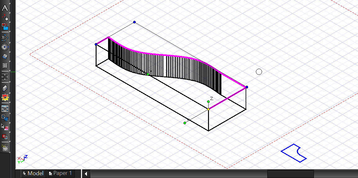
First we'll put the profile path exactly on the top of the 3D part. Select the Profile path and make sure to place the Reference dot (yellow dot) down to the left side of this one (see the image below). Help you with the snap modes Vertex and Intersection activated


If you prefer the video version of this tutorial, use this link to see it :
https://youtu.be/1m5h1R9_m34

Click on the Reference dot, place the Profile path exactly at the same position on the 3D part as shown below.


Select the Shape of the molding and place the Reference dot on the top left corner. Place it on the lower left corner as shown below


Now you'll place the shape of the molding in the good orientation to do the Sweep operation

You'll do this in 2 steps. The first one you will place this shape flat on the right side of the 3D part and in a second time you will place it perpendicular to this side of the 3D part

First step, with always the shape of the molding selected, TAB until you the Rot Y case in the Inspector bar at the bottom of the Turbocad and type 90 then press the Enter key


Now you have this position for your molding shape


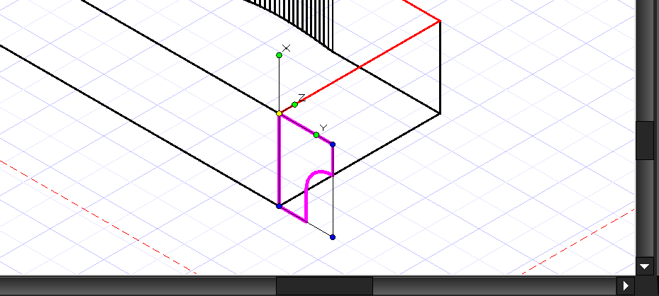
Second step, you will proceed exactly in the same manner as the step one. With always the shape of the molding selected, TAB until you the Rot Y case in the Inspector bar at the bottom of the Turbocad and type 90 then press the Enter key. You must have this orientation and location as shown below.


It's almost done ! You will do the most interesting part of this tuto

Now you will doing the new 3D part (molding) with the 2D shape you just placed and the profile path you placed before

Now select the Sweep tool from the Toolbar


 Right click anywhere in the drawing area and make sure the Use Compound Profile is turned ON and the Rigid Sweep command is turned OFF


Now select the molding shape, and select the path profile (red one). Right click and select the Finish Selection of Path command


I think at this time you want to see the final result :-) Select the Advanced or Quality rendering mode. As you can see your new 3D molding fit perfectly with the shape of the 3D part


Congratulations you have succeeded !!


Note : The Sweep tool is available with the Professionnal and PRO Platinum versions of Turbocad.  These 2 versions are available in free trial and fully functional versions for 30 days :-) Click on the links in blue to learn more

Want more Turbocad tutorials, click here

Jean
Turbocad affiliate

Turbocad, the real Alternative

samedi 18 mars 2017

Turbocad truc - Cases de l'Inspector Bar (Barre d'inspection) trop petites

An ENGLISH version of this Tutorial is available at this adress

Les cases dans l'Inspector Bar (Barre d'inspection) sont trop petites? Ce tutoriel vous montrera comment les redimensionner avec une taille confortable


D'abord, l'Inspector Bar (Barre d'inspection) est celle situé au bas de la fenêtre de Turbocad. Souvent, par défaut, les cases sont trop petites et n'afficher pas toutes les informations qui doivent y apparaître (cases titres et mesures)


Pour redimensionner les cases, pointez votre curseur entre deux cases. Deux flèches apparaissent (gauche et droite). Clic gauche, maintenez enfoncée et déplacez vers la gauche ou vers la droite jusqu'à ce que vous trouviez la bonne taille.


C'est tout !


Autre astuce: pour créer de l'espace dans la barre d'inspection, sélectionnez n'importe quel objet sur votre dessin et cliquez avec le bouton droit. Sélectionnez Properties 2D du sélecteur (ou Properties 3D) et allez à la sous-section de l'Inspector bar (barre d'Inspection) et décochez les cases que vous n'avez pas de besoin


Vous voulez plus de tutoriels sur Turbocad, allez à cette adresse

Jean
Affilié Turbocad affiliate

Turbocad, l'Alternative
Turbocad, the real Alternative


samedi 11 mars 2017

Turbocad tip - Cases in Inspector Bar too Smalls

La version en Français est disponible à cette adresse

Cases in the Inspector bar are too small ? This tutorial will show you how to resize them with a comfortable size


First, the Inspector Bar is the one located at the bottom of the Turbocad's window. Often, by default the cases are too small and don't display all informations (cases titles and measures)

To resize the cases, point your cursor between two cases. Two arrows appear (left and right). Left clic, hold down and move left and right til you find the right size. 


That's it !


Another tip : To make space in the inspector bar, select any object on your drawing and right clic. Select Selector 2D Properties (or 3D Properties) and go to Inspector bar sub section and unchecked items you d'ont need to be displayed


Wants more Turbocad tutorials, go to this adress

Jean
Turbocad affiliate

Turbocad, the real Alternative


jeudi 2 mars 2017

Turbocad - The Window tool

La version en FRANÇAIS de ce tutoriel se trouve à cette adresse

The Window tool allows you to create a Window Style and insert it directly into a wall


The Window tool allows you to create a Window Style with its own characteristics (dimensions, type, ect.) And insert it directly into a wall created with the Wall tool I describe its use in this tutorial or download one of these files depending on the version of your Turbocad : Version 2014 and ultérior  Version 2015 and ultérior


note : the Window tool is available on versions Turbocad Deluxe, Turbocad Professionnal et Turbocad Pro Platinum. These 3 versions are available in free trial version and fully functional for 30 days :-)  Click on the links in blue to learn more

Ce que ce tutoriel vous propose :


  • Create a window style with the Style manager
  • How to access the Window tool
  • Inserting a window into a wall created with the "Wall" tool of Turbocad


Create a window style with the Styles manager

Before going further you must define the size of your window as well as the height of the head of it. Access the Window tool from the Architecture - Doors, Windows and openings -- Window pull-down menu


Right click on its icon, the Properties window opens, click on the category Window main


Enter the following values:


  • Width : Enter your window width. For the tutorial requirements enter 4 feet (1220mm)
  • Height : Enter your window height. For the purpose of the tutorial enter 5 feet (1524mm)
  • Case Outside frame or Inside frame : Choose here if the width and height of the window is defined outside or inside the frame
  • Vertical alignment : select Head of object
  • Head height : Enter here at what height, with respect to the bottom of the wall, the head of the window will be located. For the purpose of the tutorial enter 7 feet (2134mm)

The other elements of this page are not the subject of this tutorial. I leave you a short description


  • Still height : not defined
  • Frame inset : the distance between the front of the wall and the window frame.
  • Open percent : percentage of window opening
  • Rise : the distance between the top corner and the top center, in the case of arched or pointed windows.
  • Leaf : In the case of irregular windows, the size of one of the panes


Styles manager as such


Access the  Style manager by scrolling the menu Tools -- Workspace -- Customize...


The Customize window opens. Select the Palettes tab and check the Style Manager and click Close at the bottom of the window


In the Style manager window, click on "+" at the left of Window styles, click once on Standard under Window styles


Push the button Create new style


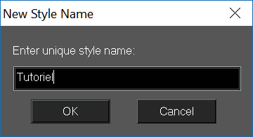
The New style name window open, Enter a name for your new window style and click on OK


Still in the Style Manager window, expand, in the Property sub-section, Dimension by clicking the "+" sign to its left. This is where you will enter the width and depth of the framing and the moldings that hold the glazing


  • Frame width : entrer 2" or 50mm
  • Frame depth : entrer 14" or 356mm fir this tutorial. Make sure that this value is slightly greater than the thickness of your wall, otherwise your window will not be visible in rendering Quality render and Advanced Render. The reason being that your window will be inserted in the center of the wall
  • Sash width : entrer 2" or 50mm
  • Sash depth : entrez 2" ou 50mm
  • Glass thickness : entrer 1/8" or 3mm
  • Auto adjust to width of wall, *** Do not check this option because it does not work well on one of the versions of Turbocad and I do not remember which one
Before continuing, you will save the changes you have just made by pressing the button Apply styles changes In the top of the Style manager window


Let's continue with the Design part or you will choose the type of window and its shape. Expand the Design part by clicking on the "+" to its left


  • Window type : For the purpose of this tutorial choose Glider (sliding) by clicking in the box next to (Value column). Turbocad offers you a choice, have fun trying them out :-)
  • Window shape : For the purpose of this tutorial choose Rectangular By clicking in the box next to it (Value column). Several other forms are also available
  • Profile : The Profile is used when you have created a profile to change the shape of the window or add holes. This option is not included in this tutorial.
  • Muntins : Offers the possibility of including a tile in the window. This option is not included in this tutorial.
  • Blocks : Offers the possibility of integrating an already created block. This option is not included in this tutorial.


Note that when you select a window type, it appears at the bottom of the Style Manager window

Remember to save the changes you just made with the Apply styles changes button as described above

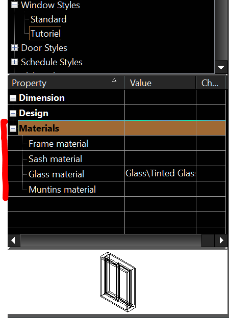
Let's finish our modifications with the Materials part. Expand it by clicking on the "+" button on its left


  • Frame material : Allows you to select the material (texture) of the window framing. To do this, simply click on the box on the right (Value column). Keep the default value for the purposes of the tutorial
  • Sash material : Allows you to select the material (texture) to use for the border that holds the glazing. To do this, simply click on the box on the right (Value column). Keep the default value for the purposes of the tutorial
  • Glass material : Allows you to select the type of glazing you want to use. For the purposes of this tutorial choose Glass -- Tinted Glass from the Materials window accessible by clicking the box next to Glass material (Value column)
  • Muntins material : Allows you to choose a material (texture) for tiling if you have one


Congratulations you have just created your first window style with the Turbocad Window tool!

note : the Window tool is available on versions Turbocad Deluxe, Turbocad Professionnal et Turbocad Pro Platinum. These 3 versions are available in free trial version and fully functional for 30 days :-)  Click on the links in blue to learn more


How to access the Window tool


To access this tool 2 choices are available to you either, through the Menu bar


Or from the drop-down menu Architecture -- Doors, Windows and openings -- Windows


Inserting a window into a wall created with the "Walltool of Turbocad


At the beginning of this tutorial you have entered the dimensions of the window, location in height of it, ect ...

Now we will set the Window tool to use the window style you have set. Right-click the Window tool icon. The Properties window opens. Click on the General category to the left of the window. At the bottom of the window in the Window styles sub-section, select the name of the style you just created. In this tutorial is Tutorial. Click the OK button


The Window tool sélected and in Isométric view, Let's get to the heart of the matter, the window insertion into the walls!

Move the cursor over the drawing surface and go along the walls. You now see a window that moves on the wall that you have chosen, you also see dimensions with measures that moves with this one. 

These dimensions describe the distances left and right between the end of the wall and the side of the window. This way you can position the window in the desired location. They are dynamic i.e. change according to the position of the window. The desired position of the window is found, click where your cursor is and the window will be inserted automatically!


To precisely position them, draw reference lines at the places you want to insert your windows on the workplane under the walls. Use the snap modes to help you locate them


You can also insert the windows in top view (Worldplan) to facilitate the task


Have fun adding window to your dream home, enlarging, new layout, ect ....  :-)


Related tutorial : The Door tool

note : the Window tool is available on versions Turbocad Deluxe, Turbocad Professionnal et Turbocad Pro Platinum. These 3 versions are available in free trial version and fully functional for 30 days :-)  Click on the links in blue to learn more

Wants more Turbocad tutorials, go to this adress

Jean
Turbocad affiliate

Turbocad, the real Alternative

Turbocad - The Door tool - Really powerfull

La version en FRANÇAIS de ce tutoriel se trouve ici

The Door tool allows you to create a door style and insert it directly into a wall

La version en FRANÇAIS de ce tutoriel se trouve ici

The Door tool allows you to create a door style with its own properties (dimensions, type, ect.) And insert it directly into a wall created with the Wall tool whose use I describe in this article or Download one of these files depending on the version of your Turbocad : Version 2014 et ultérior  Version 2015 et ultérior


note : The Door tool is available on the Turbocad Deluxe, Turbocad Professional and Turbocad Pro Platinum versions. These 3 versions are available in free trial version and fully functional for 30 days :-) Click on the links in blue to learn more

What this tutorial offers you:

  • Create a door style with Style Manager
  • How to access the Door tool
  • Inserting a door into a wall created with the tool "Wall" of Turbocad


Create a door style with Style Manager

Before going further you must define the size of your door as well as the height of the head of it. Access the Door tool from the drop-down menu Architecture -- Doors Windows and openings -- Door


Right click on its icon, the Properties window opens, click on the category Door main


Enter the following values:


  • Width : Enter your door width. For the purposes of the tutorial enter 34" (864mm)
  • Height : Enter your door width. For the purposes of the tutorial enter 7 feets(2134mm)
  • Outside of frame or Inside of frame : Choose here if the width and height of the door can be defined outside or inside the frame
  • Vertical alignment : select Head of object
  • Head height : Enter here at what height, with respect to the bottom of the wall, the head of the window will be located. For the purpose of the tutorial enter 7 feet (2134mm)

The other elements of this page are not the subject of this tutorial. I leave you a short description


  • Thershold : not defined
  • Frame inset : The distance between the front of the wall and the door frame.
  • Open percent : Percentage of door opening, 50% corresponds to 90 degrees
  • Rise : The distance between the upper corner and the upper center, in the case of  doors with arc or point.
  • Leaf : In the case of irregular doors, the size of one of the panels

Styles manager as such

Access the Style Manager by unrolling menu Tools - Workspace - Customize ... 


The Customize window opens. Select the Palettes tab and check the Style Manager and click Close at the bottom of the window


In the Style Manager window, click the "+" button to the left of Door styles, then click Standard once under Door styles


Press the button Create new style


The New style name window poen, Enter a name for your new door style and click OK


Still in the Style Manager window, expand, in the Property sub-section, Dimension by clicking the "+" sign to its left. This is where you enter the width and depth of the chassis


Translation will be completed soon, please come back later :-)
  • Frame width : entrer 2" or 50mm
  • Frame depth :  Enter 14 "or 356mm for this tutorial Make sure that this value is slightly greater than the thickness of your wall otherwise your door will not be visible in render Quality render and Advanced Render The reason is that your door will be inserted in Center of the wall
  • Stop width : entrer 2" or 50mm
  • Stop depth : entrez 2" or 50mm
  • Door thickness : entrer 1 3/4" (44mm)
  • Glass thickness : For door types including travel. This item is not included in this tutorial
  • Auto adjust to width of wall, *** Do not check this option because it does not work well on one of the versions of Turbocad and I do not remember which one

Before continuing, you will save the changes you just made by pressing the Apply styles changes button at the top of the Style Manager window


Let's continue with the Design section or you will choose the type of door and its shape. Expand the Design part by clicking on the "+" to its left


  • Door type : For the purposes of this tutorial choose Single by clicking in the box next to (Value column). Turbocad offers you a choice, have fun trying them out :-)
  • Door shape : For the purpose of this tutorial choose Rectangular by clicking in the box next to (Value column). Several other forms are also offered to you to try them!
  • Profile : The Profile is used when you have created a profile to change the shape of the door or add holes. This option is not included in this tutorial.
  • Muntins : Offers the possibility of including a tile in the glazing of a door. This option is not included in this tutorial.
  • Blocks : Offers the possibility of integrating an already created block. This option is not included in this tutorial.

Note that when you select a door type it is displayed at the bottom of the Style Manager window

Remember to save the changes you just made with the Apply styles changes button as described above


I'm just scratching the Materials part. Expand it by clicking on the "+" button on the left. I give you a brief description of the options it offers


  • Frame material : Allows you to select the material (texture) of the door frame. To do this, simply click on the box on the right (Value column). Keep the default value for the purposes of the tutorial
  • Stop material : Allows you to select the material (texture) to use for the stop that holds the door. To do this, simply click on the box on the right (Value column). Keep the default value for the purposes of the tutorial
  • Panel material : Allows you to select the material (texture) to use for the door itself (panel). To do this, simply click on the box on the right (Value column). Keep the default value for the purposes of the tutorial
  • Glass material : vous permet de sélectionner le type de vitrage que vous voulez utiliser si votre porte en comporte un. To do this, simply click on the box on the right (Value column). Keep the default value for the purposes of the tutorial
  • Muntins material : Allows you to choose a material (texture) for the glazing tile if your door has one. Keep the default value for the purposes of the tutorial

Congratulations you have just created your first door style with the Turbocad Door Tool!

Note: The Door tool is available on the Turbocad Deluxe, Turbocad Professional and Turbocad Pro Platinum versions. These 3 versions are available in free trial version and fully functional for 30 days :-) Click on the links in blue to learn more


How to access the Door tool


To access this tool 2 choices is offered to you either, by the Menu bar


Or by the drop down menu Architecture -- Doors Windows and openings -- Door


Inserting a door into a wall created with the "Walltool of Turbocad


At the beginning of the article you have entered the dimensions of the door, location in height of it, ect ...

Now we will set the Door tool to use the Door Style you have set. Right-click the Door tool icon. The Properties window opens. Click on the General category to the left of the window. At the bottom of the window in the Door styles sub-section, select the name of the style you just created. In this tutorial is Tutoriel. Click the OK button


The Door tool selected and in Isometric view, let's get to the heart of the matter, inserting doors into the walls!

Move the cursor over the drawing surface and go along the walls. You now see a door that moves on the wall that you have chosen, you also see dimensions with measures that moves with this one.

These dimensions describe the distances, left and right, between the end of the wall and the side of the door. In this way you can position the door in the desired position. They are dynamic i.e. change according to the position of the door. The desired position of the door is found, click where your cursor is and the door is automatically inserted!


To position them precisely, draw reference lines at the places you want to insert your doors onto the workplane under the walls. Use the snap modes to help you locate them


You can also insert your doors in view of the top (Worldplan) to facilitate the task


Have fun adding doors to your dream home, enlarging, new layout, ect .... :-)


nte : The Door tool is available on versions Turbocad Deluxe, Turbocad Professionnal and Turbocad Pro Platinum. These 3 versions are available in free trial version and fully functional for 30 days :-)  Click on the links in blue to learn more about

Wants more Turbocad tutorials, go to this adress

Jean
Turbocad affiliate

Turbocad, the real Alternative