Aucun message portant le libellé 2D. Afficher tous les messages

dimanche 23 avril 2017

TurboCAD - Revolve tool - How to Create a Revolution of a 2D entity around an axis

TurboCAD, How to create a circular 3D modeling shape since a 2D shape and an Axis


Sometimes it is useful to create a circular object since an irregular shape like a mecanical part or a gallery pole. This tutorial will show how to create them. Let's begin !


Note : The Revolve tool is available with the DeluxeProfessionnal and PRO Platinum versions of Turbocad.  These 3 versions are available in free trial and fully functional versions for 30 days :-) Click on the links in blue to learn more

To follow this tutorial properly, please download my Turbocad file since this link an open it

Where to find the Revolve tool ? You can find in the 3D Modify tool bar (see image below)


When you select the Revolve tool, Turbocad ask you (bottom of the screen) to select a "2D Entity to Revolve". Select the Blue one. The object becomes highlight


At the bottom left of the screen, it will ask you to "Specify the first point of the Revolution Axis "Select one of the ends of the object". After Turbocad ask you "Specify the second point of the Revolution Axis". Select the other end point of the object. The 2 points you choose deterrmine the orientation of the axis on wich the 2D shape will make a revolution. The 3D shape appear. Congratulations you just did your first Revolved hape in 3D
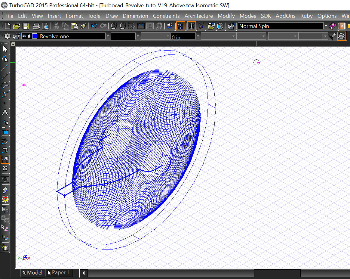

As you can see there's 2 objects, the 2D basic shape and the 3D one you can Edit, Copy ect...Now I'm sure you want to see the 3D object in rendering mode, just choose on of the rendering mode (Hidden lines, Quality or Advanced) in the Rendering modes tool bar
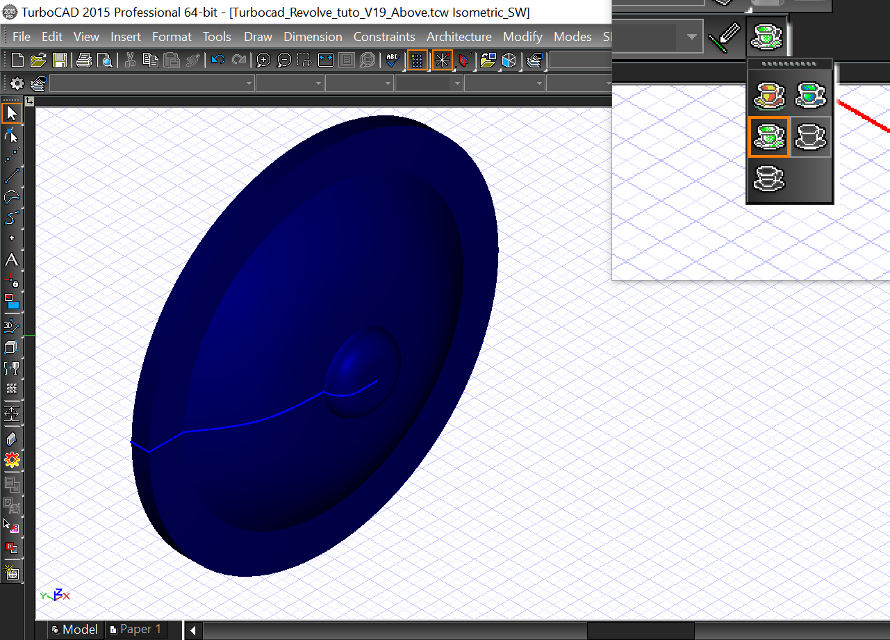


An Extra for this tutorial !


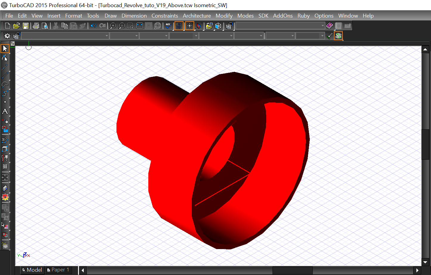
Now use the same manner to Revolve the other object and I'll show you something else will interested you, The Shell tool use to remove the interior of a Revolved 3D object made since a closed 2D polyline shape and just leaved a thickness around the object
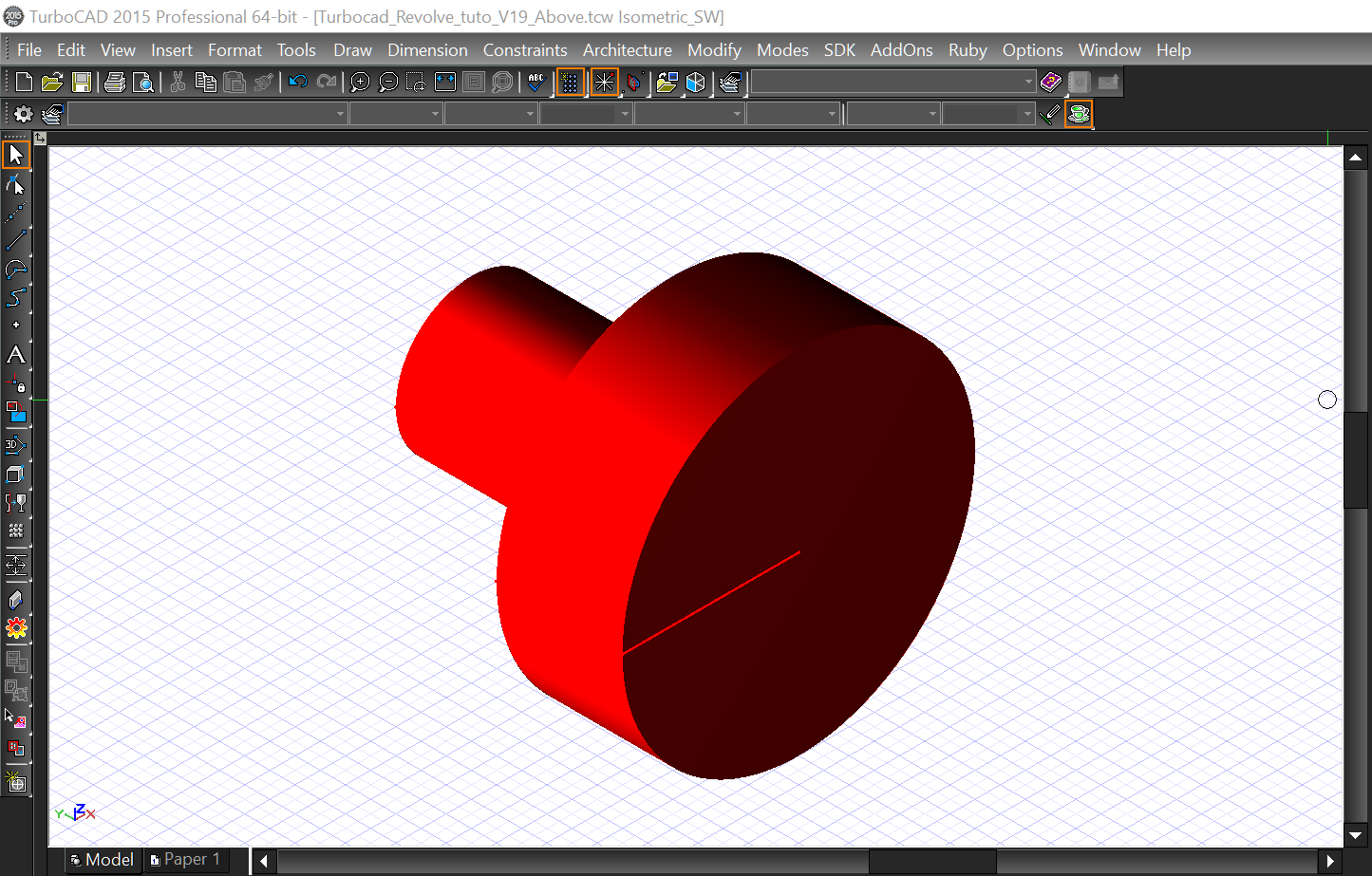

Select the Shell Solid tool from the drop down menu Modify -- Modify 3D object -- Facet Editing -- Shell Solid. At the bottom left of the Turbocad window, Place the cursor in the Thickness case and enter the value 0.5 in than press the Enter key. Select the object you just did. Turbocad ask you  to "Select a face to Omit or choose Finish from the local menu". Select the bigger round surface, right click and select the Finish command. Voilà the Shell Solid command had removed the interior of the object. Don't forget you can do it only with 3D revolved shape made with a CLOSED 2D shape.

Note : The Solid Shell tool is available with the  Professionnal and PRO Platinum versions of Turbocad.  These 2 versions are available in free trial and fully functional versions for 30 days :-) Click on the links in blue to learn more

Thanks to take your time to read this tutorial !

Want more Turbocad tutorialsclick here

Jean
Turbocad affiliate

Turbocad, the real Alternative


samedi 22 avril 2017

Turbocad -- Outil Sweep - Comment créé un objet 3D le long d'un chemin (objet)

25 janvier 2021, j'ai fait une version revisitée de ce tutoriel avec Turbocad Platinum 2020. Je vous invite à le consulter à cette adresse :-)

Comment créer un objet 3D le long d'un chemin (Path) avec un profil 2D (objet)


L'outil Sweep est utile lorsque vous souhaitez créer un objet 3D sur un chemin (path) à partir de formes en 2D. Turbocad vous permet de le faire vraiment simplement. Par exemple: une moulure autour d'un mobilier, une plinthe sur un mur de pièce, une moulure de type O'gee au plafond et mille autres applications!


Note : L'outil Sweep est disponible avec les versions Professionnal et PRO Platinum de Turbocad. Ces 2 versions sont disponibles en version d'essai gratuite et en version entièrement fonctionnelle pendant 30 jours :-) Cliquez sur les liens en bleu pour en savoir plus

Pour faciliter votre tâche, vous pouvez télécharger mon fichier Turbocad avec les objets de base dont vous aurez besoin pour ce tutoriel. Vous pouvez le télécharger avec ce lien

Une fois téléchargée, ouvrez-le. Vous trouvez les objets que nous utiliserons dans ce tutoriel soit la nouvelle moulure en 2D (en bleu) qui épousera la forme en 3D (en noir) comprenant ses deux embouts et sa face avant, j'ai aussi dessiné le chemin (path) de ces côtés (en rouge). La nouvelle moulure suivra ce chemin en réalité.


Tout d'abord, nous mettrons le chemin du profil (Path) exactement sur le haut de l'objet en 3D. Sélectionnez le chemin du profil et assurez-vous de placer le point de référence (point jaune) sur le côté gauche en bas de celui-ci (voir l'image ci-dessous). Aidez-vous avec les Snap modes Vertex et Intersection actifs


Cliquez sur le point de référence, placez le chemin du profil exactement à la même position sur l'objet en 3D, comme indiqué ci-dessous.


Sélectionnez la forme de la moulure et placez le point de référence dans le coin supérieur gauche. Placez la moulure sur le coin inférieur gauche de l'objet en 3D (noir) comme indiqué ci-dessous


Maintenant, mettez la forme de la moulure dans la bonne orientation pour effectuer l'opération Sweep

Vous ferez cela en 2 étapes. La première, placez cette forme à plat sur le côté droit de l'objet en 3D et, dans un second temps, placez la perpendiculairement à ce côté de l'objet en 3D


Première étape, toujours avec la forme de la moulure sélectionnée, appuyez sur la touche TAB jusqu'à ce que la case Rot Y soit sélectionnée dans la barre d'Inspection au bas de la fenêtre Turbocad et tapez 90 puis appuyez sur la touche Entrée


Maintenant, vous avez cette position pour votre forme de moulure


Deuxième étape, vous procéderez exactement de la même manière que la première étape. Toujours avec la forme de la moulure sélectionnée, appuyez sur la touche TAB jusqu'à ce que la case Rot Y soit sélectionnée dans la barre d'Inspection au bas de la fenêtre Turbocad et tapez 90 puis appuyez sur la touche Entrée. Vous devez avoir cette orientation et cet emplacement tel qu'indiqué ci-dessous.


C'est presque fini ! Maintenant Vous allez faire la partie la plus intéressante de ce tutoriel

Maintenant, vous allez faire la nouvelle partie 3D (moulure) avec la forme 2D que vous venez de placer et avec le chemin (path) de profil que vous avez placé avant


Sélectionnez maintenant l'outil Sweep dans la barre d'outils


Cliquez avec le bouton droit n'importe où dans la zone de dessin et assurez-vous que l'option Use Compound Profile est activé et que la commande Rigid Sweep est désactivée


Sélectionnez maintenant la forme de la moulure et sélectionnez le profil du chemin (rouge). Cliquez avec le bouton droit de la souris et sélectionnez la commande Finish Selection of Path


Je pense qu'à ce moment-ci vous voulez voir le résultat final :-) Sélectionnez le mode de rendu Advanced ou Quality. Comme vous pouvez voir votre nouvelle moulure 3D s'adapte parfaitement à la forme de l'objet 3D (noir)


Félicitations, vous avez réussi !!

Note : L'outil Sweep est disponible avec les versions Professionnal et PRO Platinum de Turbocad. Ces 2 versions sont disponibles en version d'essai gratuite et en version entièrement fonctionnelle pendant 30 jours :-) Cliquez sur les liens en bleu pour en savoir plus

Vous voulez plus de tutoriels Turbocad, cliquez ici

Jean
Affilié Turbocad affiliate

Turbocad, l'Alternative
Cliquez sur le lien en bleu pour en faire l'expérience

lundi 10 avril 2017

Turbocad Sweep tool Tutorial - How to make a 3D object along a path

La version en français de ce tutoriel est disponible à cette adresse internet

How to create a 3D object along a path with a 2D profile (object)


It is useful when you want to make a 3D part along a path from the 2D shapes. Turbocad allows you to do it really simply. For example : a molding around a furniture, a baseboard on a room wall and thousand others applications !


Note : The Sweep tool is available with the Professionnal and PRO Platinum versions of Turbocad.  These 2 versions are available in free trial and fully functional versions for 30 days :-) Click on the links in blue to learn more

To make it easier for you, you can dowload my Turbocad file with the basics objects you'll need this tutorial. You can download it with this link

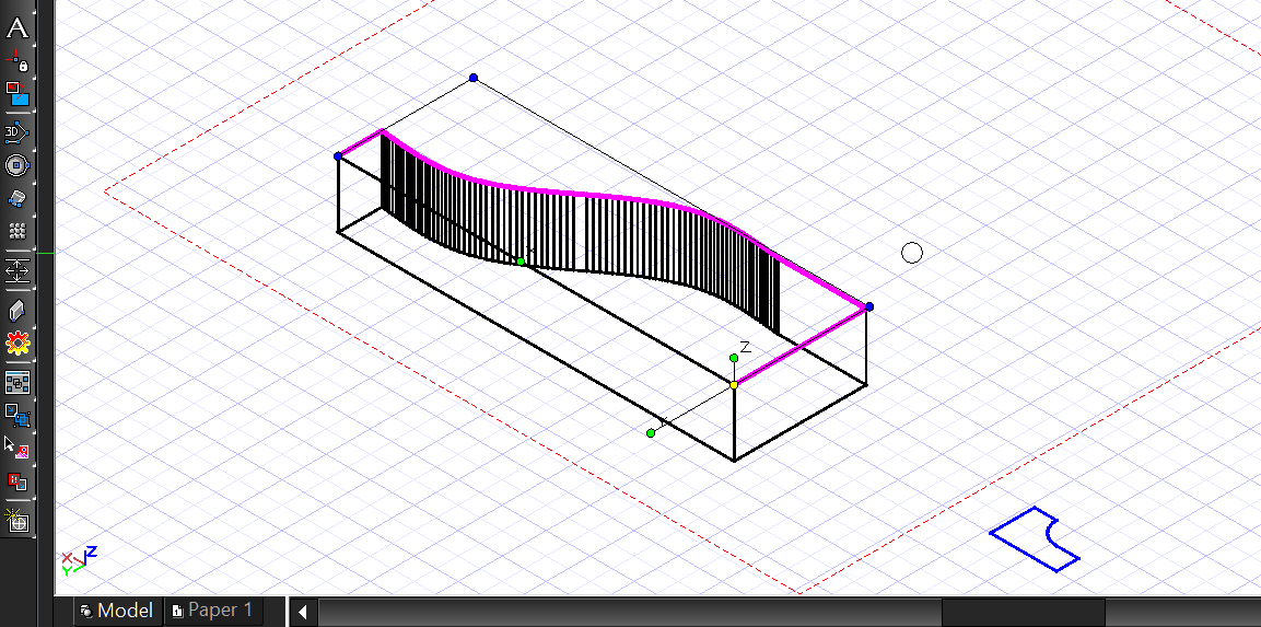
Once downloaded, open it. You find the objects we will use in this tutorial. The 3D part (black one), the new molding will follow the shape including two ends side and the front side, I draw the path profile of those sides (red one), the new molding will follow this path in reality. Finally the shape of the molding, the blue one


First we'll put the profile path exactly on the top of the 3D part. Select the Profile path and make sure to place the Reference dot (yellow dot) down to the left side of this one (see the image below). Help you with the snap modes Vertex and Intersection activated


If you prefer the video version of this tutorial, use this link to see it :
https://youtu.be/1m5h1R9_m34

Click on the Reference dot, place the Profile path exactly at the same position on the 3D part as shown below.


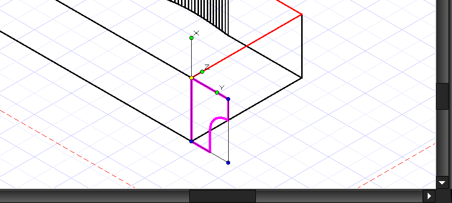
Select the Shape of the molding and place the Reference dot on the top left corner. Place it on the lower left corner as shown below


Now you'll place the shape of the molding in the good orientation to do the Sweep operation

You'll do this in 2 steps. The first one you will place this shape flat on the right side of the 3D part and in a second time you will place it perpendicular to this side of the 3D part

First step, with always the shape of the molding selected, TAB until you the Rot Y case in the Inspector bar at the bottom of the Turbocad and type 90 then press the Enter key


Now you have this position for your molding shape


Second step, you will proceed exactly in the same manner as the step one. With always the shape of the molding selected, TAB until you the Rot Y case in the Inspector bar at the bottom of the Turbocad and type 90 then press the Enter key. You must have this orientation and location as shown below.


It's almost done ! You will do the most interesting part of this tuto

Now you will doing the new 3D part (molding) with the 2D shape you just placed and the profile path you placed before

Now select the Sweep tool from the Toolbar


 Right click anywhere in the drawing area and make sure the Use Compound Profile is turned ON and the Rigid Sweep command is turned OFF


Now select the molding shape, and select the path profile (red one). Right click and select the Finish Selection of Path command


I think at this time you want to see the final result :-) Select the Advanced or Quality rendering mode. As you can see your new 3D molding fit perfectly with the shape of the 3D part


Congratulations you have succeeded !!


Note : The Sweep tool is available with the Professionnal and PRO Platinum versions of Turbocad.  These 2 versions are available in free trial and fully functional versions for 30 days :-) Click on the links in blue to learn more

Want more Turbocad tutorials, click here

Jean
Turbocad affiliate

Turbocad, the real Alternative

jeudi 23 mars 2017

Turbocad - How to Create and modifiy Blocks

Blocks, Powerful TurboCAD tool by its creation and modification as you will see !


One of the powerful tools of CAD (computer aided design) software including Turbocad is to create a block with many objects (line, curve, polyline, box, ect...) who will be copy or duplicate many times in your drawing and the beauty is when you do a modification on the Block will be done automatically on every Block insert in your drawing. Of course Blocks can be create with 3D objects too !


Create a block


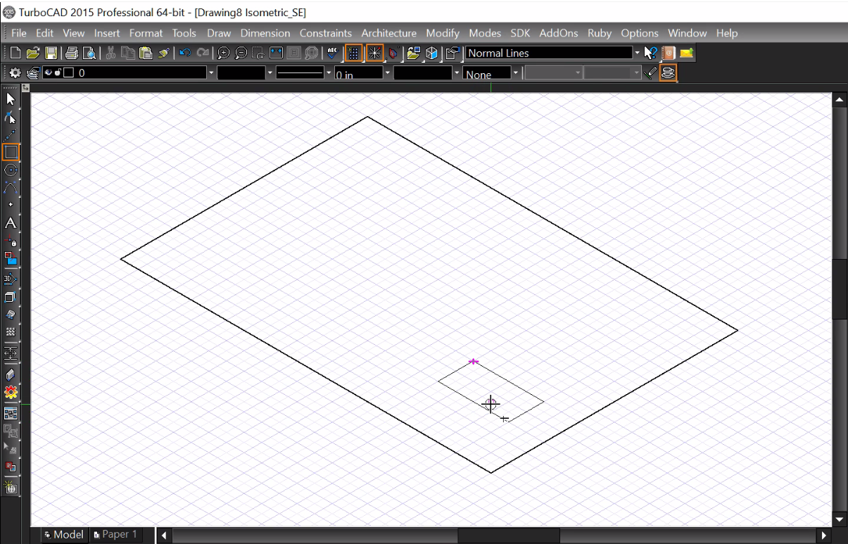
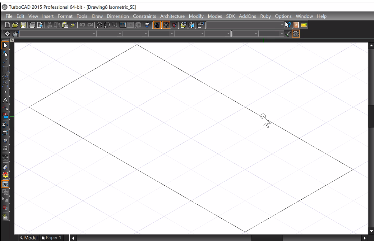
To start, open a New drawing (Ctrl + N) and choose New from Scratch. If you don't see the Grid press once on the Show / Hide Grid icon on the top of the Turbocad window (or Ctrl + G). Select the SE Isometric view (Alt + Page down). Finally, zoom out once to have something similar as the image below

Note: You can create Blocks on the Turbocad Deluxe, Turbocad Professional, Turbocad Pro Platinum and Designer (2D blocks only) versions. These 4 versions are available in free trial version and fully functional for 30 days :-) Click on the links in blue to learn more


Select the Rectangle tool from the Line toolbar, draw a rectangle covering the display that will represent a floor. Draw another rectangle, smaller, that will represent a desk. See the image below. Click on to enlarge it


Note : if you prefer to see this tutorial in video version, click on this one below


Select the smaller rectangle and drop it in the Blocks Palette or use the keybord shortcut Shift + Alt + B. To open the useful Blocks Palette, use the keyboard shortcut Ctrl + Shift + B
The Create Block window open. Give the name Desk under the Block name. Click Ok


The block you just create disappear from the drawing area. To keep a copy of your bloc on the drawing area in the same time you create the block, go to the Options drop down menu and click on the Auto naming item and check the box Insert Blocks when creating

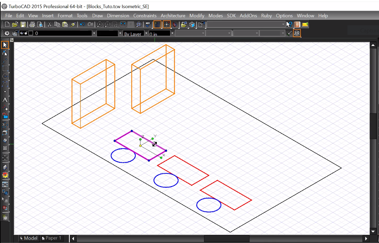
Now, insert the block you just create by click and hold (Blocks Palette) on it and drag it in the drawing area. Copy this block twice with the Rubber stamp or Copy tool accessible with the Right click. See the image below

To represent a chair, draw a Circle on the down side of a desk and create a Block with it as describe above. Copy and place two copies on the down side of the 2 others Desk. See the image below


As I told you can create Blocks with 3D objects. You will create one with the box tool. Select the Box tool in the drop down menu Draw -- 3D objects -- 3D Primitive -- Box and draw a box looks like similar as the imge below. Make a Block with it as describe above and make a copy of this block


Note: You can create Blocks on the Turbocad Deluxe, Turbocad Professional, Turbocad Pro Platinum and Designer (2D blocks only) versions. These 4 versions are available in free trial version and fully functional for 30 days :-) Click on the links in blue to learn more

Modifying Blocks


Now you will modifying Blocks. Go to the Blocks Palette (Shift + Alt + B) and select the Desk block. Press the Edit Content just over the block. A new drawing appears for the duration of modifications


Select the Rectangle, change the color for a blue, change the thickness of the line for 0.02in and press the Escape key. You can see the changes you did.


To finish the Edition, click on the Finish Edit Content in the Block Palette just over the blocks icons


As you can see, the changes you did appears on all Desk block in the drawing area !


In the same way, you will do changes on the chair blocks and the boxes blocks

Chair blocks, change the color for red and line thickness for 0.02in
Box blocks, change the color for Coral and the line thickness for 0.02in


Add objects in a Block

In the Blocks Palette, select the Desk block. Click on the Edit Content icon, the edit drawing area appears. Select the Irregular Polygon tool from the Line toolbar and draw a triangle in the desk rectangle. Right click and press Finish. Select the Triangle and change the thickness of the line for 0.02in. Click on the Finish Edit Content icon


Congratulations, you have create and modify your first blocks :-)

Want more Turbocad tutorials, click here

Note: You can create Blocks on the Turbocad Deluxe, Turbocad Professional, Turbocad Pro Platinum and Designer (2D blocks only) versions. These 4 versions are available in free trial version and fully functional for 30 days :-) Click on the links in blue to learn more

Jean
Affiliate Turbocad
Turbocad, the real Alternative