Aucun message portant le libellé shape. Afficher tous les messages

dimanche 23 avril 2017

TurboCAD - Revolve tool - How to Create a Revolution of a 2D entity around an axis

TurboCAD, How to create a circular 3D modeling shape since a 2D shape and an Axis


Sometimes it is useful to create a circular object since an irregular shape like a mecanical part or a gallery pole. This tutorial will show how to create them. Let's begin !


Note : The Revolve tool is available with the DeluxeProfessionnal and PRO Platinum versions of Turbocad.  These 3 versions are available in free trial and fully functional versions for 30 days :-) Click on the links in blue to learn more

To follow this tutorial properly, please download my Turbocad file since this link an open it

Where to find the Revolve tool ? You can find in the 3D Modify tool bar (see image below)


When you select the Revolve tool, Turbocad ask you (bottom of the screen) to select a "2D Entity to Revolve". Select the Blue one. The object becomes highlight


At the bottom left of the screen, it will ask you to "Specify the first point of the Revolution Axis "Select one of the ends of the object". After Turbocad ask you "Specify the second point of the Revolution Axis". Select the other end point of the object. The 2 points you choose deterrmine the orientation of the axis on wich the 2D shape will make a revolution. The 3D shape appear. Congratulations you just did your first Revolved hape in 3D
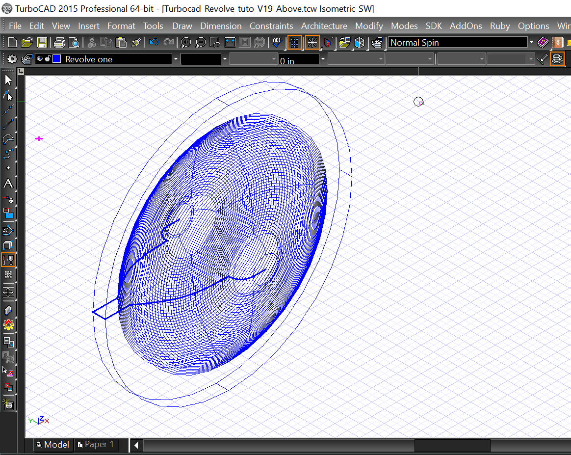

As you can see there's 2 objects, the 2D basic shape and the 3D one you can Edit, Copy ect...Now I'm sure you want to see the 3D object in rendering mode, just choose on of the rendering mode (Hidden lines, Quality or Advanced) in the Rendering modes tool bar
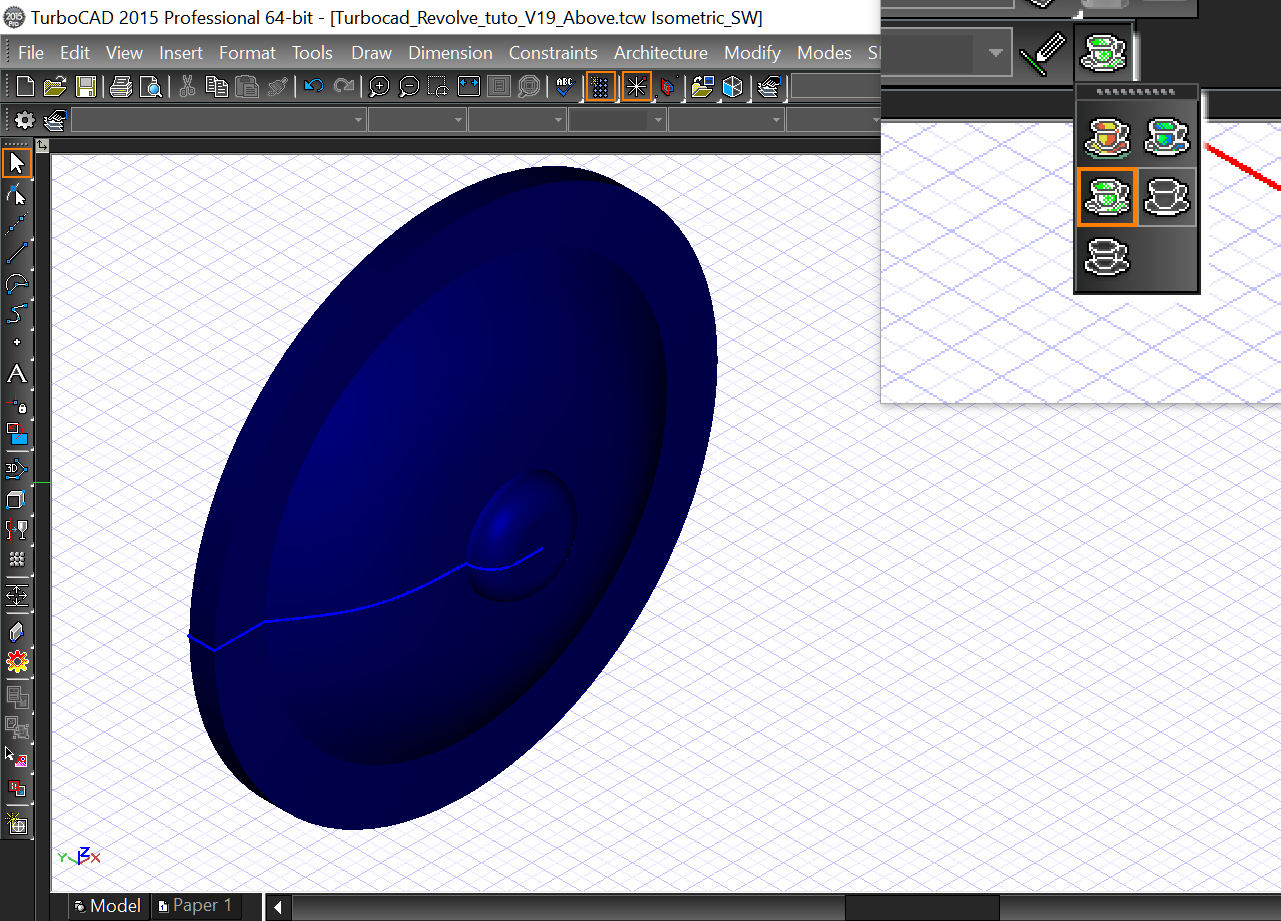


An Extra for this tutorial !


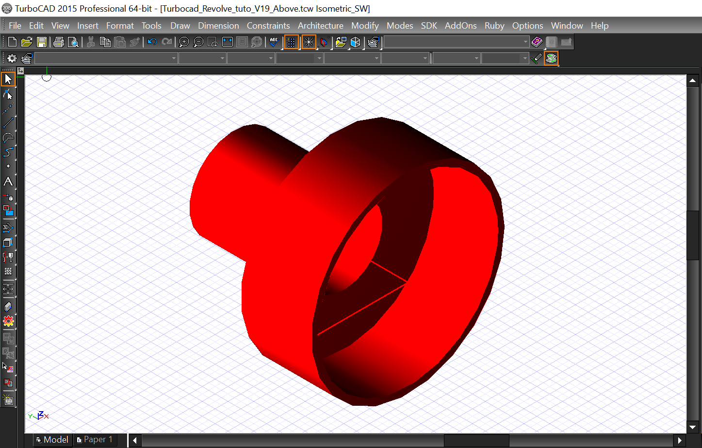
Now use the same manner to Revolve the other object and I'll show you something else will interested you, The Shell tool use to remove the interior of a Revolved 3D object made since a closed 2D polyline shape and just leaved a thickness around the object
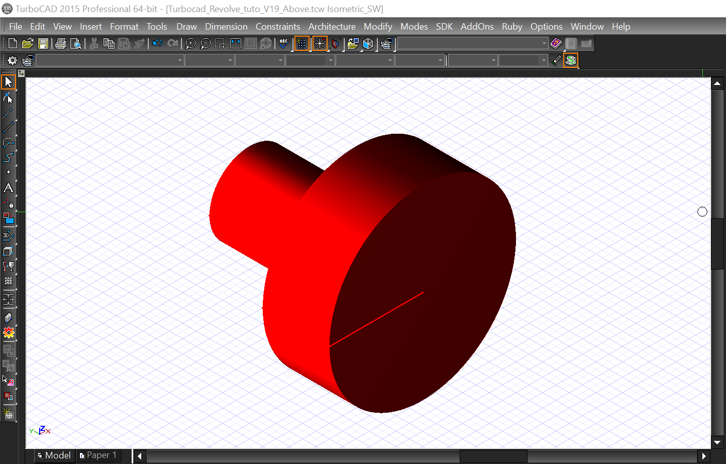

Select the Shell Solid tool from the drop down menu Modify -- Modify 3D object -- Facet Editing -- Shell Solid. At the bottom left of the Turbocad window, Place the cursor in the Thickness case and enter the value 0.5 in than press the Enter key. Select the object you just did. Turbocad ask you  to "Select a face to Omit or choose Finish from the local menu". Select the bigger round surface, right click and select the Finish command. Voilà the Shell Solid command had removed the interior of the object. Don't forget you can do it only with 3D revolved shape made with a CLOSED 2D shape.

Note : The Solid Shell tool is available with the  Professionnal and PRO Platinum versions of Turbocad.  These 2 versions are available in free trial and fully functional versions for 30 days :-) Click on the links in blue to learn more

Thanks to take your time to read this tutorial !

Want more Turbocad tutorialsclick here

Jean
Turbocad affiliate

Turbocad, the real Alternative


lundi 10 avril 2017

Turbocad Sweep tool Tutorial - How to make a 3D object along a path

La version en français de ce tutoriel est disponible à cette adresse internet

How to create a 3D object along a path with a 2D profile (object)


It is useful when you want to make a 3D part along a path from the 2D shapes. Turbocad allows you to do it really simply. For example : a molding around a furniture, a baseboard on a room wall and thousand others applications !


Note : The Sweep tool is available with the Professionnal and PRO Platinum versions of Turbocad.  These 2 versions are available in free trial and fully functional versions for 30 days :-) Click on the links in blue to learn more

To make it easier for you, you can dowload my Turbocad file with the basics objects you'll need this tutorial. You can download it with this link

Once downloaded, open it. You find the objects we will use in this tutorial. The 3D part (black one), the new molding will follow the shape including two ends side and the front side, I draw the path profile of those sides (red one), the new molding will follow this path in reality. Finally the shape of the molding, the blue one


First we'll put the profile path exactly on the top of the 3D part. Select the Profile path and make sure to place the Reference dot (yellow dot) down to the left side of this one (see the image below). Help you with the snap modes Vertex and Intersection activated


If you prefer the video version of this tutorial, use this link to see it :
https://youtu.be/1m5h1R9_m34

Click on the Reference dot, place the Profile path exactly at the same position on the 3D part as shown below.


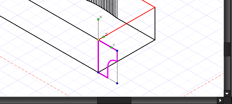
Select the Shape of the molding and place the Reference dot on the top left corner. Place it on the lower left corner as shown below


Now you'll place the shape of the molding in the good orientation to do the Sweep operation

You'll do this in 2 steps. The first one you will place this shape flat on the right side of the 3D part and in a second time you will place it perpendicular to this side of the 3D part

First step, with always the shape of the molding selected, TAB until you the Rot Y case in the Inspector bar at the bottom of the Turbocad and type 90 then press the Enter key


Now you have this position for your molding shape


Second step, you will proceed exactly in the same manner as the step one. With always the shape of the molding selected, TAB until you the Rot Y case in the Inspector bar at the bottom of the Turbocad and type 90 then press the Enter key. You must have this orientation and location as shown below.


It's almost done ! You will do the most interesting part of this tuto

Now you will doing the new 3D part (molding) with the 2D shape you just placed and the profile path you placed before

Now select the Sweep tool from the Toolbar


 Right click anywhere in the drawing area and make sure the Use Compound Profile is turned ON and the Rigid Sweep command is turned OFF


Now select the molding shape, and select the path profile (red one). Right click and select the Finish Selection of Path command


I think at this time you want to see the final result :-) Select the Advanced or Quality rendering mode. As you can see your new 3D molding fit perfectly with the shape of the 3D part


Congratulations you have succeeded !!


Note : The Sweep tool is available with the Professionnal and PRO Platinum versions of Turbocad.  These 2 versions are available in free trial and fully functional versions for 30 days :-) Click on the links in blue to learn more

Want more Turbocad tutorials, click here

Jean
Turbocad affiliate

Turbocad, the real Alternative