mercredi 29 mars 2017

Turbocad - Simple Extrude - Simple way on How to transform 2D in 3D objects

Want to visualize your 2D drawings objects in 3D modelisation? The Turbocad Simple Extrude tool will be your friend to do this !


You can download the Turbocad starting file for this tutorial by clicking this link


Access the Simple Extrude tool by the toolbar or go to the Draw -- 3D objects -- 3D Based -- Simple Extrude


Note: the Simple Extrude tool is including in versions Turbocad Deluxe, Turbocad Professional, Turbocad Pro Platinum. These 3 versions are available in free trial version and fully functional for 30 days :-) Click on the links in blue to learn more

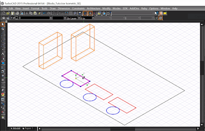
To simply extrude and object once you had selected the Simple Extrude tool, select and object and automaticaly an height of a 3D shape from this 2D object appears. You can define the new height of this object arbitrarily above or down the object or enter a precise value (positive or negative) in the height box at the bottom of the Turbocad window and press Enter key


If you want to complete this tutorial, enter these dimensions

Back of the couch (red rectangle) : 5 inches
Arms of the couch (coral rectangles): 3.5 inches
Cushion of the couch (magenta rectangle) : 2 inches
Round table (blue circle) : 2 inches
Corner table (green polygone) : 2 inches

These new 3D objects can be edit or modify like any others 3D objects

Note: the Simple Extrude tool is including in versions Turbocad Deluxe, Turbocad Professional, Turbocad Pro Platinum. These 3 versions are available in free trial version and fully functional for 30 days :-) Click on the links in blue to learn more

Jean
Affiliate Turbocad
Turbocad, the real Alternative

jeudi 23 mars 2017

Turbocad - How to Create and modifiy Blocks

Blocks, Powerful TurboCAD tool by its creation and modification as you will see !


One of the powerful tools of CAD (computer aided design) software including Turbocad is to create a block with many objects (line, curve, polyline, box, ect...) who will be copy or duplicate many times in your drawing and the beauty is when you do a modification on the Block will be done automatically on every Block insert in your drawing. Of course Blocks can be create with 3D objects too !


Create a block


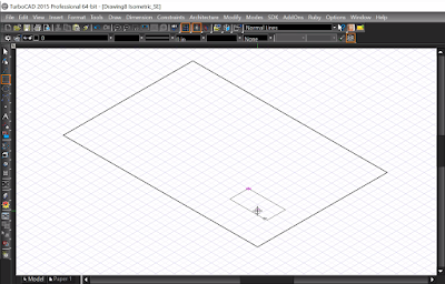
To start, open a New drawing (Ctrl + N) and choose New from Scratch. If you don't see the Grid press once on the Show / Hide Grid icon on the top of the Turbocad window (or Ctrl + G). Select the SE Isometric view (Alt + Page down). Finally, zoom out once to have something similar as the image below

Note: You can create Blocks on the Turbocad Deluxe, Turbocad Professional, Turbocad Pro Platinum and Designer (2D blocks only) versions. These 4 versions are available in free trial version and fully functional for 30 days :-) Click on the links in blue to learn more


Select the Rectangle tool from the Line toolbar, draw a rectangle covering the display that will represent a floor. Draw another rectangle, smaller, that will represent a desk. See the image below. Click on to enlarge it


Note : if you prefer to see this tutorial in video version, click on this one below


Select the smaller rectangle and drop it in the Blocks Palette or use the keybord shortcut Shift + Alt + B. To open the useful Blocks Palette, use the keyboard shortcut Ctrl + Shift + B
The Create Block window open. Give the name Desk under the Block name. Click Ok


The block you just create disappear from the drawing area. To keep a copy of your bloc on the drawing area in the same time you create the block, go to the Options drop down menu and click on the Auto naming item and check the box Insert Blocks when creating

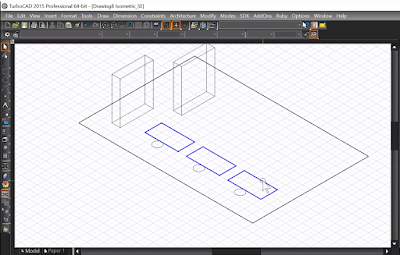
Now, insert the block you just create by click and hold (Blocks Palette) on it and drag it in the drawing area. Copy this block twice with the Rubber stamp or Copy tool accessible with the Right click. See the image below

To represent a chair, draw a Circle on the down side of a desk and create a Block with it as describe above. Copy and place two copies on the down side of the 2 others Desk. See the image below


As I told you can create Blocks with 3D objects. You will create one with the box tool. Select the Box tool in the drop down menu Draw -- 3D objects -- 3D Primitive -- Box and draw a box looks like similar as the imge below. Make a Block with it as describe above and make a copy of this block


Note: You can create Blocks on the Turbocad Deluxe, Turbocad Professional, Turbocad Pro Platinum and Designer (2D blocks only) versions. These 4 versions are available in free trial version and fully functional for 30 days :-) Click on the links in blue to learn more

Modifying Blocks


Now you will modifying Blocks. Go to the Blocks Palette (Shift + Alt + B) and select the Desk block. Press the Edit Content just over the block. A new drawing appears for the duration of modifications


Select the Rectangle, change the color for a blue, change the thickness of the line for 0.02in and press the Escape key. You can see the changes you did.


To finish the Edition, click on the Finish Edit Content in the Block Palette just over the blocks icons


As you can see, the changes you did appears on all Desk block in the drawing area !


In the same way, you will do changes on the chair blocks and the boxes blocks

Chair blocks, change the color for red and line thickness for 0.02in
Box blocks, change the color for Coral and the line thickness for 0.02in


Add objects in a Block

In the Blocks Palette, select the Desk block. Click on the Edit Content icon, the edit drawing area appears. Select the Irregular Polygon tool from the Line toolbar and draw a triangle in the desk rectangle. Right click and press Finish. Select the Triangle and change the thickness of the line for 0.02in. Click on the Finish Edit Content icon


Congratulations, you have create and modify your first blocks :-)

Want more Turbocad tutorials, click here

Note: You can create Blocks on the Turbocad Deluxe, Turbocad Professional, Turbocad Pro Platinum and Designer (2D blocks only) versions. These 4 versions are available in free trial version and fully functional for 30 days :-) Click on the links in blue to learn more

Jean
Affiliate Turbocad
Turbocad, the real Alternative


mardi 21 mars 2017

Turbocad - How to Insert a Window into a door


Inserting a door into a wall is good, but a door with a window is better!


You have seen in the tutorial on the tool "Door" of Turbocad, available at this address, how to insert a door in a wall create with the tool "Wall". In this tutorial you will see how to create a glazing with tiling in a door created with the Door tool.


For the purpose of this tutorial, you can download the basic walls to these addresses:

Version 2014 and ulterior   
Version 2015 and ulterior


Note: The Door tool is available on the Turbocad Deluxe, Turbocad Professional and Turbocad Pro Platinum versions. These 3 versions are available in free trial version and fully functional for 30 days :-) Click on the links in blue to learn more


Create the  Door


Before going further you will enter the basic values of the door are its dimensions and its vertical position with respect to the floor. Right click on the Door tool icon, the Properties window opens


Enter the following values in the corresponding fields:


  • Width: Enter your door width. For the purpose of the tutorial enter 34 "(864mm)
  • Height: Enter your door height. For the purpose of the tutorial enter 7 feet (2134mm)
  • Outside of frame or Inside of frame: Choose here whether the width and height of the door is defined on the outside or inside the frame
  • Vertical alignment: Select Head of object
  • Head height: Enter here at what height, relative to the bottom of the wall, the head of the window will be located. For the purpose of the tutorial enter 7 feet (2134mm)


Here I will give you the main steps to follow to create it, you can refer to my tutorial "Turbocad - the tool Door - Really powerful" to get the complete steps to create it

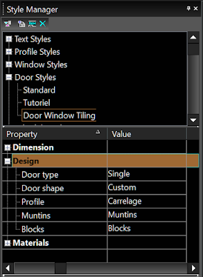
Go to the Style Manager, expand the Door styles item and select Standard. Then click the Create new style icon in the icon bar under Style manager


The New style name window appears, enter a name for your new door. For the needs of the tutorial I will use Door Window Tiling


Now under Door Styles, click once on your new door name


Further down in the Style Manager window you will find the Dimension item, expand it.


Enter the following values in the corresponding fields

  • Frame width, enter 2 "or 50mm
  • Frame depth, enter 14 "or 356mm for this tutorial. Make sure that this value is slightly greater than the thickness of your wall otherwise your door will not be visible in renderings Quality render and Advanced Render The reason being that your window will be inserted in the center of the wall
  • Stop width, enter 1 "or 25mm
  • Stop depth, enter 2 "or 50mm
  • Door thickness: Enter 1 3/4 "(44mm)
  • Glass thickness, for the purpose of this tutorial enter 1/8 "(3mm)
  • Auto adjust to width of wall *** do not check this option because it does not work well on one of the versions of Turbocad and I do not remember which one


Now expand item


  • Door type: For the purposes of this tutorial choose Single by clicking in the box next to it (Value column). Turbocad offers you a choice, have fun trying them out :-)
  • Door shape: For the purposes of this tutorial choose Rectangular by clicking in the box next to it (Value column). Several other forms are also offered to you to try them!
  • Profile: The Profile is used when you create your profile for the insertion of your glazing. Do not select Profile, we'll go back later in this tutorial
  • Muntins: You will use this option to include your tile. Leave this field as we will go back later in this tutorial
  • Blocks: Offers the possibility to integrate an already created block. This option is not included in this tutorial.


Save the fruit of your work by clicking on the Apply Style Changes icon


Now expand the item Materials, The only item you'll change here is the Glass material 


Click in the right field (Value) of Glass material, the Materials window opens. Enter the values corresponding to those in the image below


Click OK and save the fruit of your work by clicking on the Apply Style Changes icon


Your door style is now created!

Note: The Door tool is available on the Turbocad Deluxe, Turbocad Professional and Turbocad Pro Platinum versions. These 3 versions are available in free trial version and fully functional for 30 days :-) Click on the links in blue to learn more


Create window and tiling


Now let's get to the heart of the matter either the glazing and the tiling that you will include in the door


Still in Style Manager, return to the Design item and click in the box to the right (Value) of Muntin, The Muntin window opens. This is where we will define the dimensions of the material that will make up the tile


Click the Add button, the Muntins block window opens, Enter the following values:


  • Name : for the purposes of this tutorial I will use Tile
  • Glass component: Select All if you have not already done so. As for the Single option, I have not experienced it yet
  • Muntin : width will be 1/2 "(13mm), Depth (depth): will be 1/2" (13mm)
  • Lights: Pattern for this tutorial will be Rectangular Lights high: for the purposes of this tutorial it will be 6, Lights wide for the purposes of this tutorial. Will be 5


The other items in this window are not included in this tutorial

Click OK.


We will now create a Profile for our window

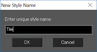
In the Style manager, click Profile Styles once and click the Create a new style button. The New Style Name window appears, enter Tile as the name and click the OK button


A blank page in Isometric view appears in the drawing space. Select the Rectangle tool, click in the drawing space and move the cursor so that a rectangle begins to be drawn as shown in the illustration below. Enter the following dimensions for this rectangle that represents your door:


Cases located at the bottom left of the Turbocad window. Size A: 84 inches (2134mm) and Size B: 34 inches (864mm)

Press Enter. Use Zoom extents (Ctrl + Backspace) to see the entire rectangle

Draw a second rectangle in the same way with the following dimensions for that other rectangle that represents your glazing:

Size A: 72 inches (1829mm) and Size B: 22 inches (559mm)

Press Enter. Use Zoom extents (Ctrl + Backspace) to see all rectangles


Now select the small rectangle and place it so that it is perfectly centered in the largest. You can use Snap Mode Middle Point and Intersection tools, Show magnetic point tool, Extended Ortho and Appearent intersection See image below


Select the two rectangles, go to the Modify menu and click Place on Workplane (Shift + Alt + W)


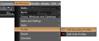
Select the Edit Boundary Profiles tool from the Architecture - Profiles - Edit Boundary Profiles drop-down menu and select the largest rectangle, right click and click Finish


Select the Edit Hole Profiles tool from the Architecture - Profiles - Edit Hole Profiles drop-down menu and select the smallest rectangle, right click and click Finish


To complete the Profile you have two choices, if you have the validation button represented by a pink hook at the top of the Style Manager window, click on it. If not, use the selection tool to select the two rectangles, right click and select Finish Block / group Editing completely at the bottom of the menu (scroll down with the small arrow at the bottom of the menu)


You return to the isometric view of the walls in 3D, return to the Style Manager and expand the Door Styles, choose the Tile style, then expand the Design section. Click in the box next to Profile and choose item Tile


Now right click on the Door tool and select Properties and go to General. At the bottom of this window, go to the Door Styles sub-section and click its drop-down menu and choose the door style you just created and click the OK button


You are now ready to insert your new doors with the Door tool :-). Select it and move your cursor and see a buddy move with dimensions at the bottom of it. They represent the distances between the end of walls and the sides of your door, in order to facilitate its location. Click where you want to place it.

Note: you can move on any walls create


Congratulations you have successfully completed the tutorial!

Note: The Door tool is available on the Turbocad Deluxe, Turbocad Professional and Turbocad Pro Platinum versions. These 3 versions are available in free trial version and fully functional for 30 days :-) Click on the links in blue to learn more

Want more Turbocad tutorials, click here

Jean

Turbocad affiliate


To be complete, come later :-)

samedi 18 mars 2017

Turbocad truc - Cases de l'Inspector Bar (Barre d'inspection) trop petites

An ENGLISH version of this Tutorial is available at this adress

Les cases dans l'Inspector Bar (Barre d'inspection) sont trop petites? Ce tutoriel vous montrera comment les redimensionner avec une taille confortable


D'abord, l'Inspector Bar (Barre d'inspection) est celle situé au bas de la fenêtre de Turbocad. Souvent, par défaut, les cases sont trop petites et n'afficher pas toutes les informations qui doivent y apparaître (cases titres et mesures)


Pour redimensionner les cases, pointez votre curseur entre deux cases. Deux flèches apparaissent (gauche et droite). Clic gauche, maintenez enfoncée et déplacez vers la gauche ou vers la droite jusqu'à ce que vous trouviez la bonne taille.


C'est tout !


Autre astuce: pour créer de l'espace dans la barre d'inspection, sélectionnez n'importe quel objet sur votre dessin et cliquez avec le bouton droit. Sélectionnez Properties 2D du sélecteur (ou Properties 3D) et allez à la sous-section de l'Inspector bar (barre d'Inspection) et décochez les cases que vous n'avez pas de besoin


Vous voulez plus de tutoriels sur Turbocad, allez à cette adresse

Jean
Affilié Turbocad affiliate

Turbocad, l'Alternative
Turbocad, the real Alternative


lundi 13 mars 2017

Turbocad - Raccourcis Clavier - Travaillez plus efficacement

692

Turbocad, pour augmenter votre efficacité....utilisez les Raccourcis clavier !


Tous les utilisateurs en puissance de logiciels de CAO (conception assisté par ordinateur) vous le diront, activez des Raccourcis par le clavier augmente de façon significative votre efficacité


Dans ce tutoriel vous verrez les Raccourcis suivants :

Cet article n'inclus que les commandes par défaut lors de l'installation. Les commandes que l'ont retrouvent dans tous les logiciels Windows ne sont pas inclus dans cet article


  • Snap modes (modes d'accrochage)
  • Menu Edit (Éditon) incluant Select by (sélectionner par)
  • Menu View (affichage)
  • Menu Insert (insertion)
  • Menu Format (formattage)
  • Menu Tools (outils)
  • Menu Modify (modification)
  • Menu Modes
  • Menu Options


Les Snap Modes (modes d'accrochage) aussi appelés SEKE's


NOM DE LA COMMANDE RACCOURCIS CLAVIER DESCRIPTION


NO SNAP
S
Désactive tout les snap modes à l’exception du mode ORTHO
CENTER
C
Accroche sur le centre d’un objet en plan
DIVIDE POINT
D
Accroche sur une division de ligne ou arc
GRID
G
Accroche sur un point de la grille
INTERSECTION
I
Accroche l’intersction de deux objets
MIDDLEPOINT
M
Accroche sur le milieu d’une ligne
NEAREST ON GRAPHIC
N
Accroche sur le point le plus près
QUADRANT POINT
Q
Accroche sur un point quadrant
VERTEX
V
Accroche sur le début ou la fin d’un objet
TANGENT TO AN ARC AND CURVE
Shift + T
Accroche sur un point tangent à un arc, cercle ou une courbe
ORTHO
Shift + O
Permet au curseur de se déplacer dans un angle précis
PROJECTION
J
Accroche à un point qui est l'image de projection perpendiculaire du dernier point dessiné sur un objet sélectionné
SHOW MAGNETIC POINT
Shift + W
Lorsqu’utilisé, un point en forme de losange apparaît sur tous les emplacements de tous les Snap modes en fonction
EXTENDED ORTHO
Shift + X
Ajustement à des points situés orthogonalement à partir de points existants


Les modes d'accrochages suivant n'ont pas de raccourcis clavier par défaut dans Turbocad mais vous pouvez en créer en cliquant sur cette adresse internet. Si vous n'êtes pas à l'aise avec l'anglais, accéder à cette adresse internet avec le navigateur Chrome, il permet la traduction en français de la page. 

  • Nearest on facet
  • Center of extents
  • Opposite point
  • Workplane intersection
  • Appearant intersection
  • Auto Workplane by face
Note : tous ces raccourcis sont inclus dans la version Pro Patinum de Turbocad, pour ce qui est des versions DeLuxe, Professionnal et Designer certains de ces racourcis et/ou commandes ne sont pas inclus. Ces 4 versions sont disponibles en version d'essai Gratuite et pleinement fonctionnellles pour 30 jours :-)  Cliquez sur les liens internet en bleu pour en apprendre plus

Menu Edit (Édition) incluant Select by (sélectionner par)

NOM DE LA COMMANDE RACCOURCIS CLAVIER DESCRIPTION


QUERY
Ctrl + Q
Sélection par questionnement
ENTITY TYPE
Ctrl + T
Sélection par type d’objets
COLOR
Ctrl + K
Sélection par couleur d’objets
LAYER
Ctrl + L
Sélection d’objets par couche
ATTRIBUTE
Ctrl + I
Sélection d’objets par attribut
CLEAR SELECTION
SUPP (DEL)
Supprime la sélection
SELECT
ESPACE (SPACE BAR)
Outil de sélection, déselectionne l’outil en cours

Menu View (affichage)


NOM DE LA COMMANDE RACCOURCIS CLAVIER DESCRIPTION


REDRAW
F5
Désactive tout les snap modes à l’exception du mode ORTHO
MODEL SPACE
Ctrl + Alt + M
Retourner en Model Space
ZOOM WINDOW
Ctrl + Shift + Espace arrière (Backspace)
Zoom une zone définie par un rectangle dessiné par l’utilisateur
FULL VIEW
Shift + Espace arrière (Backspace)
Vue entière du dessin
EXTENTS (View)
Ctrl + Espace arrière (Backspace)
Vue entière du dessin
PAN TO POINT
Ctrl + Alt +P
Centre le dessin sur le point cliquer à l’écran
AERIAL VIEW
F4
Sélectionnez un espace rectangulaire pour créer un vue aérienne sceondaire

Menu View (affichage) - CAMERA


NOM DE LA COMMANDE RACCOURCIS CLAVIER DESCRIPTION


PROPERTIES (CAMERA)
Ctrl + Alt + C
Accéder aux propriétés de la caméra
PlaceToDrawingCenter
Ctrl + D
Place la caméra au centre du dessin
LOOK TO DRAWING CENTER
Ctrl + Shift + D
Défini le point d’intérêt au centre du dessin
ROTATE LEFT (CAMERA ROLL)
Shift + Flèche gauche
Rotation de la caméra vers la gauche
ROTATE RIGHT (CAMERA ROLL)
Shift + Flèche droite
Rotation de la caméra vers la droite
TURN LEFT (CAMERA TURN)
Ctrl + Fèche gauche
Tourne la caméra vers la gauche
TURN RIGHT (CAMERA TURN)
Ctrl + Fèche droite
Tourne la caméra vers la droite
TURN UP (CAMERA TURN)
Ctrl + Fèche haut
Tourne la caméra vers le haut
TURN DOWN (CAMERA TURN)
Ctrl + Fèche bas
Tourne la caméra vers le bas


3D Views (vues en 3 dimensions)

NOM DE LA COMMANDE RACCOURCIS CLAVIER DESCRIPTION


PLAN – BY WORLD
Ctrl + W
À définir
PLAN – BY WORKPLANE
Ctrl + Shift + W
À définir
TOP
Alt + flèche haut
Dessin vu du dessus
BOTTOM
Alt + flèche Bas
Dessin vu du dessous
LEFT
Alt + flèche gauche
Vue gauche du dessin
RIGHT
Alt + flèche droite
Vue droite du dessin


FRONT
Alt + Début (Home)
Vue frontale du dessin
BACK
Alt + Fin (End)
Vue arrière du dessin
SW ISOMETRIC
Alt + Page précédente
Vue isométrique Sud-Ouest
SE ISOMETRIC
Alt + Page suivante
Vue isométrique Sud-est
NE ISOMETRIC
Shift + Alt + Page suivante
Vue isométrique Nord-est
NW ISOMETRIC
Shift + Alt + Page précédente
Vue isométrique Nord-ouest


Display


NOM DE LA COMMANDE RACCOURCIS CLAVIER DESCRIPTION


WORLD COORDINATE SYSTEM (UCS Icon)
Ctrl + U
À définir
USER COORDINATE SYSTEM (UCS Icon)
Ctrl + Shift + U
À définir
GRID
Alt + G
Affiche la Grille
APERTURE (Curseur)
Shift + Alt + A
Curseur en mode ouverture
CROSSHAIR (Curseur)
Shift + Alt + C
Curseur en forme de croix pleine grandeur
ISOMETRIC (Curseur)
Shift + Alt + I
Curseur en forme de croix incluant l’axe des Z


Note : tous ces raccourcis sont inclus dans la version Pro Patinum de Turbocad. Pour ce qui est des versions DeLuxeProfessionnal et Designer certains de ces raccourcis et/ou commandes ne sont pas inclus dans ces versions. Ces 4 versions sont disponibles en version d'essai Gratuite et pleinement fonctionnellles pour 30 jours :-)  Cliquez sur les liens internet en bleu pour en apprendre plus

Visual styles (styles visuels)


NOM DE LA COMMANDE RACCOURCIS CLAVIER DESCRIPTION


HIDDEN LINES
Ctrl + Alt + H
Régénère un modèle 3D en supprimant les lignes cachées 
DRAFT RENDER
Ctrl + Alt + D
Créer une image ombragée de fil de fer en 3D
QUALITY RENDER
Ctrl + Alt + Q
Créez une image réaliste d'un cadre filaire 3D


Menu Insert (insérer)


BLOCKS
Ctrl + Shift + B
Montre ou cache la palette Blocks
CREATE EXTERNAL REFERENCE
Shift + Alt + X
Défini un fichier comme référence externe à un dessin
HYPERLINK
Ctrl + H
Défini un Hyperlien


Menu Format


NOM DE LA COMMANDE RACCOURCIS CLAVIER DESCRIPTION


FORMAT PAINTER
Ctrl + Shift + P
Copier des propriétés d'un objet à un autre.
CREATE BLOCK
Shift + Alt + B
Outil de création de block
CREATE A GROUP
Shift + Alt + G
Outil de création de groupe d’objets


Menu Tools

Initial


NOM DE LA COMMANDE RACCOURCIS CLAVIER DESCRIPTION


QUICK SELECT
Ctrl + I
Sélection rapide par type d’objet, attribut
BLOCKS
Ctrl + Shift + B
Affiche d’un bloc. Un bloc est une collection d'objets combinés en un seul objet
RELOCATE BLOCK / SPACE REFERENCE POINT
Ctrl + Shift + R
Relocalisation de n’importe quel point de référence
EDIT GROUP CONTENT
Ctrl + G
Édition d’un groupe d’objets (Group)
FINISH EDIT GROUP
Ctrl + Shift + G
Terminer la commande Edit Group Content
OPTIONS
Ctrl + Shift + O
Acéder aux options de la fenêtre Program Setup


Palettes


NOM DE LA COMMANDE RACCOURCIS CLAVIER DESCRIPTION


SELECTION INFO
Ctrl + Shift + I
Affiche des informations sur l'objet ou les objets sélectionnés
MEASUREMENT INFO
Ctrl + Shift + T
Affiche les mesures calculées par les outils Mesure
BLOCKS
Ctrl + Shift + C
Affiche d’un bloc. Un bloc est une collection d'objets combinés en un seul objet
DESIGN DIRECTOR
F3
Panorama (palette) pour effectuer des commandes sur les couches, plans de travail (Workplane), vues, caméras et objets graphiques ou groupe d'objets
ENVIRONNEMENTS
Ctrl + Shift + E
Fournit un accès facile et rapide aux environnements de Turbocad
LIBRARY
Ctrl + Shift + S
La bibliothèque (Library) TurboCAD permet d'accéder aux symboles et
les pièces. Les symboles et les parties, comme les blocs et les groupes, sont des objets disponible pour utilisation répétée
LUMINANCES
Ctrl + Shift + L
Fournit un accès facile et rapide aux effets de la lumière sur les objets.
MATERIALS
Ctrl + Shift + M
Fournit un accès facile et rapide aux matériaux appliqués sur les objets


Note : tous ces raccourcis sont inclus dans la version Pro Patinum de Turbocad. Pour ce qui est des versions DeLuxeProfessionnal et Designer certains de ces raccourcis et/ou commandes ne sont pas inclus dans ces versions. Ces 4 versions sont disponibles en version d'essai Gratuite et pleinement fonctionnellles pour 30 jours :-)  Cliquez sur les liens internet en bleu pour en apprendre plus

Draw Order


NOM DE LA COMMANDERACCOURCIS CLAVIERDESCRIPTION


BRING TO FRONT
Shift + Page up
Place le ou les objets sélectionnés en avant plan
SEND TO BACK
Shift Page down
Place le ou les objets sélectionnés en arrière plan

New UCS (nouveau Système de coordonnées utilisateur)


NOM DE LA COMMANDE RACCOURCIS CLAVIER DESCRIPTION


BY VIEW
Ctrl + Shit + V
Définir le plan de travail par la vue active
BY WORLD
Ctrl + Alt + W
Définition du plan de travail par système de coordonnées mondial (WCS)
BY ENTITY
Ctrl + Alt + G
Définir le plan de travail à celui d'une entité (objet)
NAMED
W
Attribuez un nom au plan de travail ou définissez un WorkPlane (plan de travail)
BY 3 POINTS
Shift + Alt + 3
Dessiner WorkPlane (Plan de travail) en utilisant trois points
BY FACET
Shift + Alt + F
Définir le plan de travail par facette


Menu Modify (modifications)


NOM DE LA COMMANDE RACCOURCIS CLAVIER DESCRIPTION


PROPERTIES
Ctrl + F
Accéder à la fenêtre des propriétés
FORMAT PAINTER
Ctrl + Shift + P
Copier des propriétés d'un objet à un autre.
PLACE ON WORKPLANE
Shift + Alt + W
Place un ou des objets sur le plan de travail en couts d’utilisation
CREATED A REGION
Shift + Alt + R
Créé une région à partir d’un objet fermé
EXPLODE
Shift + Alt + E
Décomposer un graphique dans ses parties constituantes


3D Boolean oprérations (opérations bouléennes en 3 dimensions)


NOM DE LA COMMANDE RACCOURCIS CLAVIER DESCRIPTION


3D ADD
Ctrl + Alt + A
Fusion de deux objets solides par opération bouléennes.
3D SUBTRACT
Ctrl + Alt + S
Soustraction d’un objet solide d’un autre objet solide
3D INTERSECT
Ctrl + Alt + I
Ne garde que la partie de deux objets solides qui s’entrecroisent
3D SLICE
Ctrl + Alt + L
Le ou les objets sélectionnés sont coupés selon le plan de travail en cours d’utilisation


2D Align


NOM DE LA COMMANDE RACCOURCIS CLAVIER DESCRIPTION


2D ALIGN – BOTTOM
Ctrl + Shit + flèche vers le bas
Aligne les entités sélectionnées en bas de la fenêtre de sélection
2D ALIGN – MIDDLE
Ctrl + Alt + Home (début)
Aligne les entités sélectionnées au centre de la fenêtre de sélection
2D ALIGN – TOP
Ctrl + Alt + flèche vers le haut
Aligne les entités sélectionnées en haut de la fenêtre de sélection
2D ALIGN – LEFT
Ctrl + Alt + flèche vers la gauche
Aligne les entités sélectionnées à gauche de la fenêtre de sélection
2D ALIGN – CENTER
Ctrl + Alt + End (fin)
Aligne les entités sélectionnées au centre de la fenêtre de sélection
2D ALIGN – RIGHT
Ctrl + Alt + flèche vers la droite
Aligne les entités sélectionnées à droite de la fenêtre de sélection


Menu Modes


NOM DE LA COMMANDE RACCOURCIS CLAVIER DESCRIPTION


LOCK X POSITION
X
Verrouille la position en X
LOCK YPOSITION
Y
Verrouille la position en Y
LOCK Z POSITION
Z
Verrouille la position en Z


Coord system (coordonnées système)


NOM DE LA COMMANDE RACCOURCIS CLAVIER DESCRIPTION


ABSOLUTE COORDS
A
Pour utiliser les coordonnées absolues
RELATIVE COORDS
R
Pour utiliser les coordonnées relatives
POLARS COORDS
P
Pour utiliser les coordonnées polaires
RELOCATE ORIGIN
L
Pour relocaliser le point d’origine


Options


NOM DE LA COMMANDE RACCOURCIS CLAVIER DESCRIPTION


PROGRAM SETUP
Ctrl + Shift + O
Permet de modifier les paramètres du programme
DRAWING SETUP
Ctrl + Alt + O
Permet de modifier les paramètres du dessin


Par le menu local (clique droit)


NOM DE LA COMMANDE RACCOURCIS CLAVIER DESCRIPTION


EDIT TOOL
Ctrl + ESpace
Sélectionne et édite les nodes. Remodeler un objet
EDIT REFERENCE POINT (RELOCATE)
D
Déplacer le point de référence

Note : tous ces raccourcis sont inclus dans la version Pro Patinum de Turbocad. Pour ce qui est des versions DeLuxeProfessionnal et Designer certains de ces raccourcis et/ou commandes ne sont pas inclus dans ces versions. Ces 4 versions sont disponibles en version d'essai Gratuite et pleinement fonctionnellles pour 30 jours :-)  Cliquez sur les liens internet en bleu pour en apprendre plus

Vous voulez plus de tutoriels sur Turbocad, allez à cette adresse

Jean
Affilié Turbocad affiliate

Turbocad, l'Alternative
Turbocad, the real Alternative